![]()
Calibrating the CMPS01, CMPS03 Robot Compass Modules
CMPS03 - Calibration procedure is the same
as CMPS01 Rev 7.
CMPS01 - As from Software revision 7, the calibration
procedure has changed. Both methods are detailed below
Calibration only needs to be done once - the calibration data is stored in EEPROM on the PIC16F872 chip. You do not need to re-calibrate every time the module is powered up. The module has already been calibrated in our workshop for our inclination, which is 67 degrees. If your location is close to this, you may like to try the compass without re-calibrating at all.
Compass module orientation to produce 0 degrees reading.
|
|
|
| Register | Function |
| 0 | Software Revision Number |
| 1 | Compass Bearing as a byte, i.e. 0-255 for a full circle |
| 2,3 | Compass Bearing as a word, i.e. 0-3599 for a full circle, representing 0-359.9 degrees. |
| 4,5 | Internal Test - Sensor1 difference signal - 16 bit signed word |
| 6,7 | Internal Test - Sensor2 difference signal - 16 bit signed word |
| 8,9 | Internal Test - Calibration value 1 - 16 bit signed word |
| 10,11 | Internal Test - Calibration value 2 - 16 bit signed word |
| 12 | Unused - Read as Zero |
| 13 | Unused - Read as Zero |
| 14 | Calibration Done Flag - Zero in calibrate mode when un-calibrated, 255 otherwise - unused in Rev 7 software & CMPS03 |
| 15 | Calibrate Command - Write 255 to enter calibrate mode, write zero to exit. See text. |
Register 0 is the Software revision number (originally 3, now 7 with new
calibration routines and 8 for the CMPS03).
Registers 14 & 15 are
used to calibrate the compass. The procedure changed with Rev 7 software. Full
calibration information is here
IMPORTANT - The compass module must be kept flat (horizontal and
parallel to the earths surface) with the components on top and for the CMPS01
the sensors underneath. Keep the module away from metallic - especially magnetic
- objects.
Calibrating Rev 3 Software - Recognized by lack of
revision number on CPU chip, or read revision number from register 0
I2C
Method
To calibrate the compass using the I2C bus, you only have to
write 255 to register 15 and rotate the module very slowly through 360° . Writing zero to register 15 will store the
calibration values in the processors internal EEPROM. Readings are taken by the
processor at four compass points and these values are used to generate the
calibration values. Register 14 reads 255 during normal operation. It
reads zero when Calibrate mode is entered and 255 again when the four compass
points have been measured. Register 14 will therefore indicate that the four
points have been acquired and that zero can be written to register 15 to store
the calibration and return to normal operation. It is necessary to rotate the
compass very slowly during calibration to avoid missing the required compass
points and to keep it horizontal to ensure the calibration figures are
accurate.
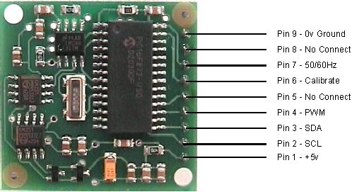
Pin Method
Pins 5,6 are used to calibrate the compass.
The calibrate input (pin 6) has an on-board pull-up resistor and can be left
unconnected after calibration. To calibrate the compass you only have to take
the calibrate pin low and rotate the module very slowly through 360° . Taking the calibrate pin high will store the
calibration values in the processors internal EEPROM. Readings are taken by the
processor at four compass points and these values are used to generate the
calibration values. The CalDone output pin (pin 5) is high during normal
operation. It goes low when the Calibrate pin is pulled low and high again when
the four compass points have been measured. The CalDone pin will therefore
indicate that the four points have been acquired and that the Calibrate pin can
be raised high again. It is necessary to rotate the compass slowly during
calibration to avoid missing the required compass points and to keep it
horizontal to ensure the calibration figures are accurate.
Calibrating Rev 7 Software - Recognized by revision number label on
CMPS01 CPU chip, or read revision number from register 0.
Also applies to
Calibrating the CMPS03 Module.
Note that pin 5 (CalDone) and
register 14 (Calibration Done Flag) are not used with Rev 7 software or the
CMPS03. Pin 5 should be left unconnected and register 14 ignored. When
calibrating the compass, you must know exactly which direction is North,
East, South and West. Don't guess at it. Get a magnetic needle compass and check
it.
I2C Method
To calibrate using the I2C bus, you only have
to write 255 (0xff) to register 15 for each of the four major compass points
North, East, South and West. The 255 is cleared internally automatically after
each point is calibrated. The compass points can be set in any order, but all
four points must be calibrated. For example
1. Set the compass module
flat, pointing North. Write 255 to register 15
2. Set the compass module
flat, pointing East. Write 255 to register 15
3. Set the compass module flat,
pointing South. Write 255 to register 15
4. Set the compass module flat,
pointing West. Write 255 to register 15
That's it.
Pin
Method
Pin 6 is used to calibrate the compass. The calibrate input (pin
6) has an on-board pull-up resistor and can be left unconnected after
calibration. To calibrate the compass you only have to take the calibrate pin
low and then high again for each of the four major compass points North, East,
South and West. A simple push switch wired from pin6 to 0v (Ground) is OK for
this. The compass points can be set in any order, but all four points must be
calibrated. For example
1. Set the compass module flat, pointing North.
Press and release the switch
2. Set the compass module flat, pointing East.
Press and release the switch
3. Set the compass module flat, pointing South.
Press and release the switch
4. Set the compass module flat, pointing West.
Press and release the switch
That's it.