Table of Contents:
- Introduction
- First steps with a PIC16F84 on a prototype
board
- More first steps letting the
led flash on the PIC16F84
- Still more first steps with a PIC16F628 on
a prototype board generating one PWM signal
- Generating two PWM signals on a PIC16F877,
still on the prototype board
- Motor electronics, H-bridge, first board
- Motor electronics, H-bridge, second board
- A small review of the Microchip IDE Mplab
and the C compiler from Hi-Tech
- Self-soldered board with PIC16F877, 2x PWM
signals, ICD interface, buttons, leds and potis
- The robot crusing around.
- Files and links and all the pictures
- About myself
- Copyright, thanks and date of last change
Introduction
The principal goal of this project is to
develop strategies and solutions for a autonomous mobile
robot which will be participating in a competition between
IUT of different French universities.
The rules for the competition are fixed,
see rules.pdf
.
The hardware for the mobile robot is fixed, see Base_roulante.pdf.
The project documentation in general is written
in English, most of the documents describing the robot are in
French. Microchip's documentation of the PIC midrange family is
in English. Sometimes, I was lazy and made some internal comments
in the source files in German.
Most of the manuals are in pdf format, if you
do not have Adobe Acrobot Reader installed I recommend installing
it now.
Link ???, ICON ???
This html report was written using Netscape's
6.2.1 builtin composer. If you have MS Windows installed on
your PC, point your browser to
www.redhat.com or www.freebsd.org
, and learn more, hurry ;).
First steps with a PIC16F84
on a prototype board
At first, I needed to get accustomed with
Microchips IDE Mplab, the eepromer and the pic family in general.
The first program was simple, see ex002.asm , and does nothing
more then switching a led on if you press a button and switching
it back off when the button is not pressed. Professor Arlotto
(at a
picture of him, too) first
had to explain the RISC way to program in assembler to me.
The PIC16F8X manual is available at Microchip's
web site at http://www.microchip.com
or localy here 16f84a.pdf .
More first steps letting the led
flash on the PIC16F84
This program was little more than cut 'n paste
from a project Professor Arlotto gave me. Understanding and verifying
it was a good way to get to know the PIC's assembler better. See
the source here, ex001.asm
(Yes, sometimes 001 comes after 002 ...) .
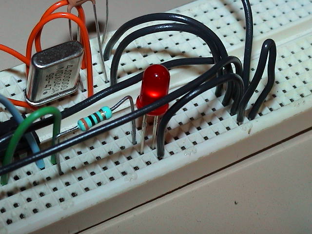
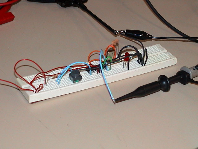
Still more first steps with a
PIC16F628 on a prototype board generating one PWM signal
Once I was more familar with the PIC, I took
a PIC16F628, attached some buttons and leds as well as a potentiometer
to it and began generating PWM signals. At the beginning with
two fixed relations between the PWM period and the duty cycle which
were choosen by pressing or releasing a button. Later on I used the
poti to read an analog value, scaled it to the 8 bits the PWM module
is offering in the MSB register and used this to generate a variable
PWM duty cycle.
See the source, pwm001.asm
.
PIC16F628 manual available at http://www.microchip.com
or here 16f62x.pdf
.
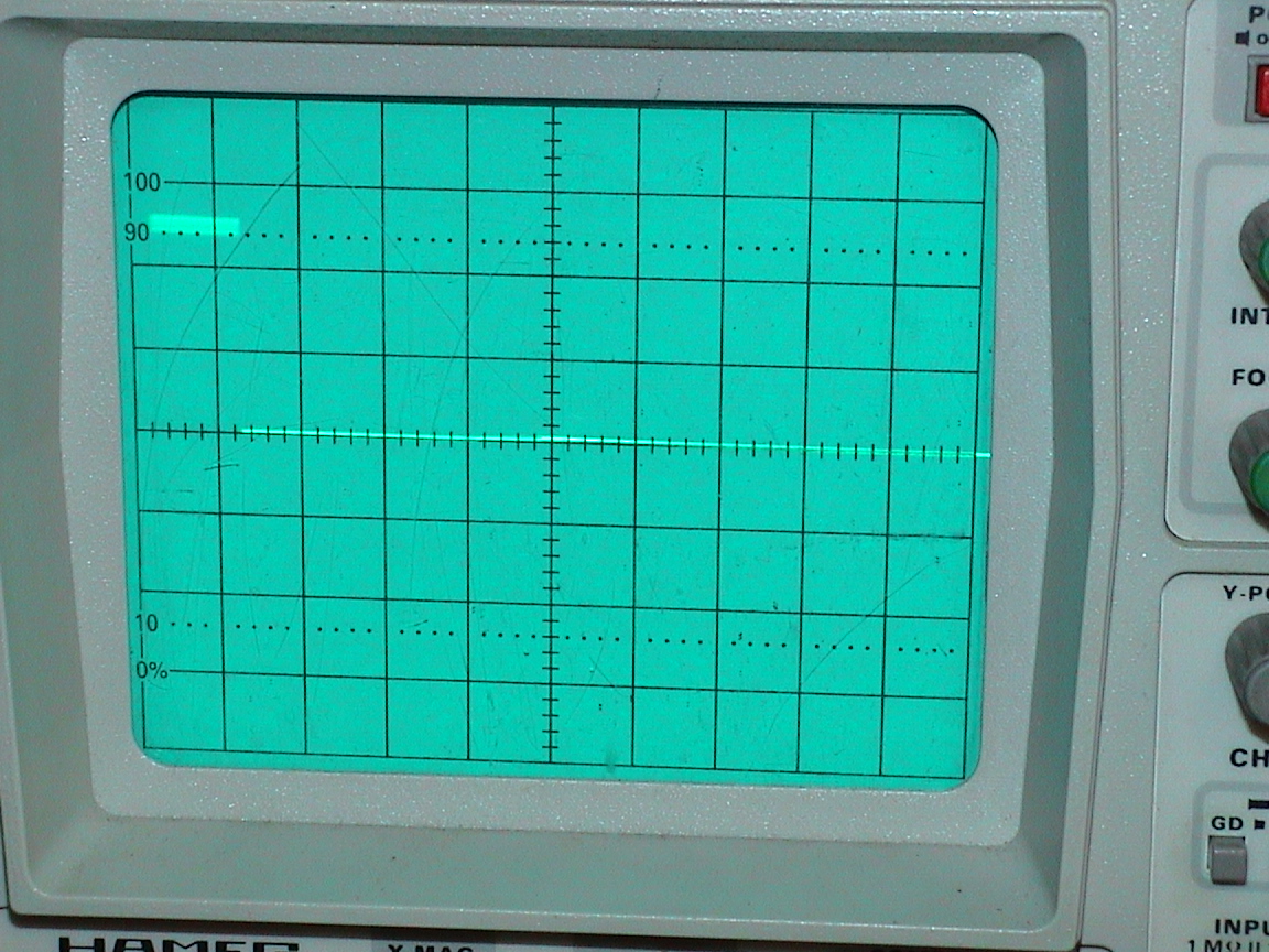
Generating two PWM signals on a
PIC16F877, still on the prototype board
Once the PWM generation was working for one
channel, I switched to the PIC16F877, which is offering two
PWM modules.
PIC16F877 manual available at http://www.microchip.com
or here 16f87x.pdf
.
There is also a mpeg
movie (~750KB) showing the scope's screen while the
PWM duty cycle is changing .
The source is again available here, pwm_f877.asm .

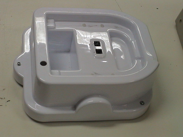
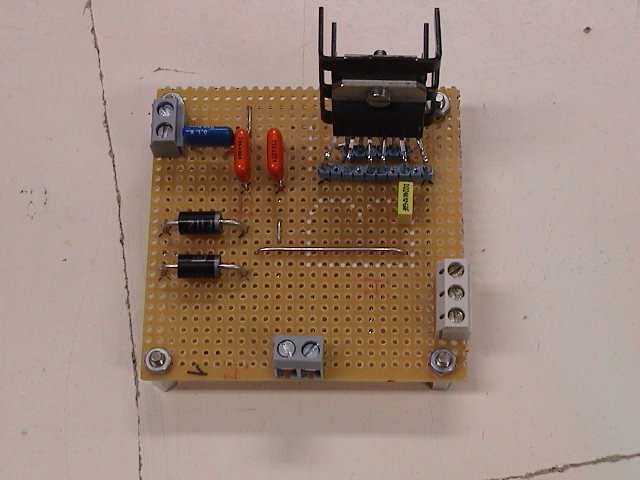
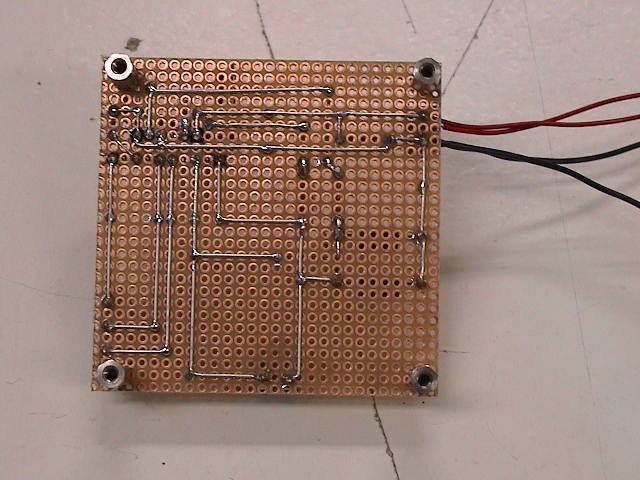
Motor electronics, H-bridge, first board
The two motor electronic boards have inputs for ground and +12V
(2 pin connector on the upper left corner), inputs for signals from the
microcontroller, ENABLE, IN1 and IN2 (3 pin connector on the lower right
side corner) and outputs to the motor (2 pin connector in the middle of
lower side).
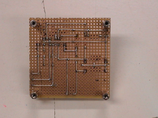
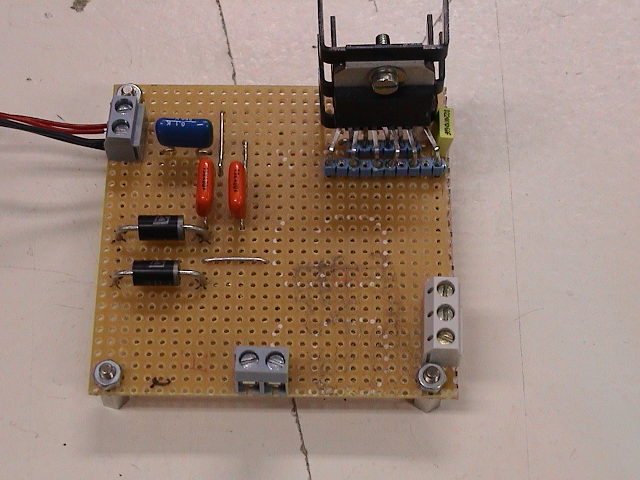
Motor electronics, H-bridge, second board
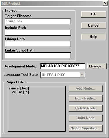
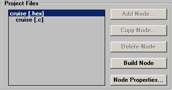
A small review of the Microchip IDE Mplab and the
C compiler from Hi-Tech


Options to select:
Informational messages: Verbose
Warning level: On 3
Generate debug info: On
Assembler Optimizations: On
Global Optimizations: On 3
Include Search path: On CD
Error file: On
Produce assembler list file: On <-- This is needed for debugging
of c code in Mplab
Compile for MPLAB-ICD: On
Strip local symbols: On
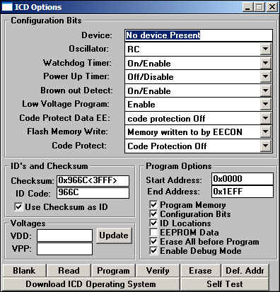
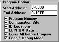
Reseting the µP via the Mplab IDE and the ICD is only working
if the chip has been programmed in "Enable Debug Mode".
Put some screenshots here
Q: When I compile a PIC program using MPLAB, the error messages from PICC
appear the in MPLAB build results window, but if I double click on the
message, MPLAB doesn't jump to the error location. How do I fix this?

A: The default error format from PICC is not what MPLAB wants. You can alter
this by setting some environment variables. These are:

HTC_ERR_FORMAT=Error[000] %f %l : %s
HTC_WARN_FORMAT=Warning[000] %f %l : %s
90. How to get
MPLAB to display compile errors
Q: When I compile an MPLAB project, I get the message:

"MPLAB is unable to find output file "XXXX.OBJ". This may be due to a compile,
assemble, or link process failure.

Build failed.",

but no errors are displayed. How do I know what is producing the error?


A: MPLAB displays any errors after it attempts to compile. These messages are
read from error files that the compiler must produce. You need to turn on the
"Error file" option for each source node in the project and the HEX link
node. In the data field for this option enter the name of the source file
with the extension ".err". So if you have a source file called "main.c",
then in the node properties for the node, you should specify an error
file of main.err. If the HEX node has the same name as one of the source
modules, then turn on the "Append Errors to file" option and enter the
error file as indicated above.
Back to top
91. How do I view
local variables in MPLAB?
To be able to view local varibles in MPLAB, be sure to compile
your project with the option "Generate Debug Info" for each node.
Also add to the HEX file node the additional command line
option -FAKELOCAL

Local variables will then be seen in the format: function_name.local_var
So for example, if you had a local variable called "number" and it
was within a function called "testing", then it would appear in the
symbol list as "testing.number"
Back to top
Incremental
Compiles with Hi-Tech C
Q. Under Hi-Tech C and MPLab, every
time I recompile, it recompiles everything and then links it. How do
I do incremental compiles?
A. Add the line 'c:\ht-pic\include' under 'include path'
in the 'edit project' dialogue to enable incremental compiles.
You must already have the 'language tool' under the root node set
to 'PIC C Linker', not 'PIC C compiler'. Add each source file to the
list to be compiled and then linked.
For instructions on how to set up a project properly to support
support libraries, additional C files, and incremental compiles, see
here.
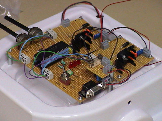
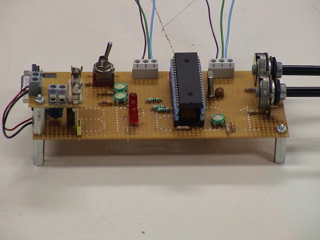
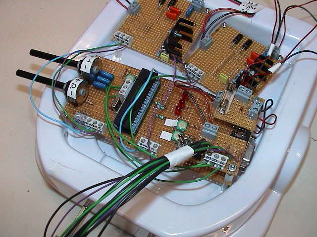
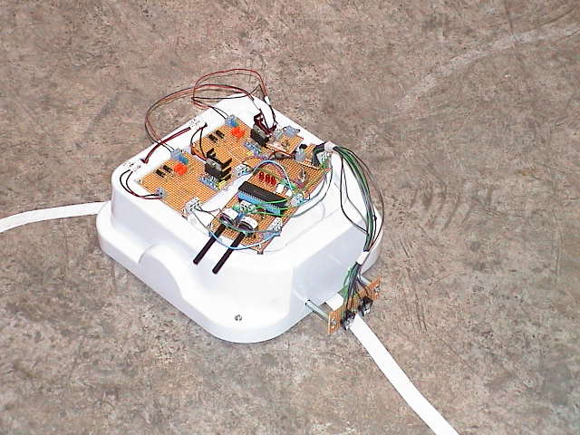
Self-soldered board with PIC16F877, 2x PWM signals,
ICD interface, buttons, leds and potis
Finally the motors where turning, but I wanted something which
I can put on the robot to see the thing cruising around. So I had to
develop a self-soldered board for the PIC16F877.
Two source files exist for this board, the first tst_boa.c was the the predecessor of the first,
but its intention was to test the board whereas the seconds cruise.c intention is to actually let the robot cruise
around.
See the robot driving around , mpeg movie
(~440KB).
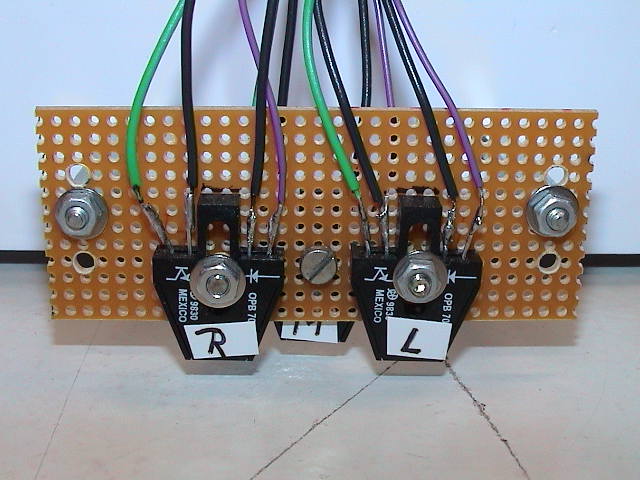
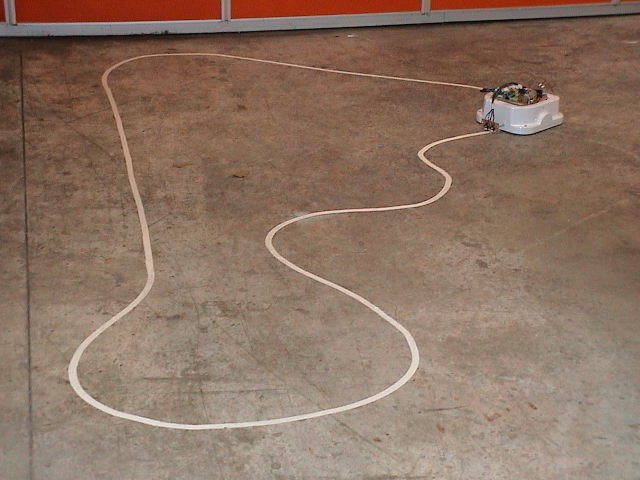
The robot crusing around.
The robot following the white scotch.
The scotch detection is down in the main loop in cruise3.c. Three different
speeds are calculated according to the potis.
The files of the project.
ad.c
ad.h
buttons.c
buttons.h
cruise3.c
cruise3.h
eeprom.c
eeprom.h
error.c
error.h
hardware.h
ports.c
ports.h
pwm.c
pwm.h
sensor.c
sensor.h
timer.c
timer.h
Button1 is used for teaching the robot which values are possible for the
light sensors. The values can change depending of the environments light and
the sensors itself. Unfortunately, not all sensors are created equal. The
values are stored in the PIC's EEprom. Button0 is used to recall these values.
Connection to the ICD module is done by a self-fabricated cable. Pinout:
DB9 on own target board
|
RJ11 ICD module
|
Color
|
PIN
|
Signal
|
Color
|
PIN
|
Signal
|
white
|
1
|
VPP
|
white
|
1
|
VPP
|
green
|
2
|
RB7
|
black
|
2
|
VDD +12V
|
yellow
|
3
|
RB6
|
red
|
3
|
GND
|
blue
|
4
|
RB3
|
green
|
4
|
RB7
|
NC
|
5
|
NC
|
yellow
|
5
|
RB6
|
red
|
6
|
GND
|
blue
|
6
|
RB3
|
black
|
7
|
VDD +12V
|
NC
|
NC
|
NC
|
NC
|
8
|
NC
|
NC
|
NC
|
NC
|
NC
|
9
|
NC
|
NC
|
NC
|
NC
|